Microfluidic-based hydrodynamic trap facilitates trapping using the sole action of fluid flow and provides a viable alternative to existing confinement and manipulation techniques based on electric, optical, magnetic or acoustic force fields for example. In this review, we describe various methods and techniques utilized in microfluidic spheroid and single-cell trapping.
Single-cell trapping processes
One of the most robust methods to analyze populations of single cells in relatively high throughput are microwell arrays.
However, a recurring problem is that microwell cultures are static. This limits their ability to actively manipulate the trapped cells, for example to change the medium or to control the exposure of the cells to mitogenic stimuli. On the other hand, microfluidic valves, optical tweezers, dielectrophoresis (DEP) and acoustic waves, which can be easily integrated with microfluidic devices, allow more powerful approaches to trapping and manipulating individual cells.
In this review, we have chosen to rely on the study of Koben et al. in 2018, in which they were able to evaluate the trapping force according to different chip designs. In their study, Koben et al. present a microfluidic device capable of trapping a single cell via a network of traps whose main channel length can be 1, 2 or 4 mm with respectively 64 traps in parallel and 3 to 10 traps in series. Each chip then has two inlets, one for medium infusion and one for cell loading.
In practice, the chip was first primed with complete cell culture medium at a flow rate of 25 ml/min and the cells were injected through the spare inlet. After closing the cell inlet with a stopper, the chip was placed on an inverted microscope, infused at a flow rate of 20 nl/min and the ratio between successful and unsuccessful traps was quantified. In order to analyse a sufficiently large number of trapping events for statistical analysis, the already trapped cells were removed from the traps by reversing the direction of flow for about 1.5 to 2 s and restarting the infusion.
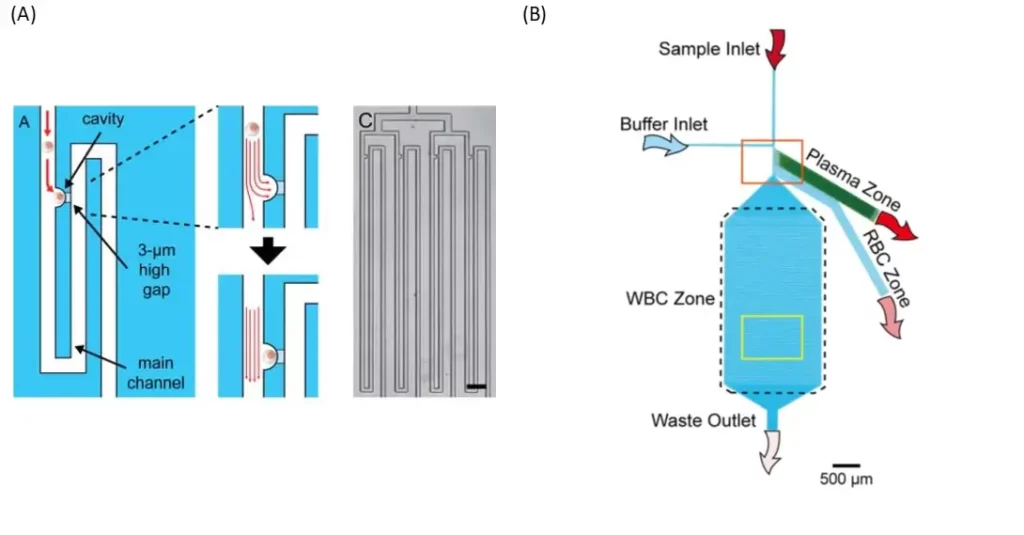
An other smart device was designed to allow the loading of a whole blood sample (fig. 1 B). It consists of a whole blood inlet, a buffer inlet and a bifurcation region, which leads to three blood component collection areas: a plasma area, a red blood cell (RBC) area and a white blood cell (WBC) area. The separation mechanism for red and white blood cells is based on the bifurcation law and the cross-flow (saline) method. The bifurcation region contains six bead-filled side channels, four narrowed side channels and one main channel for plasma extraction, red blood cell extraction and white blood cell trapping, respectively. In order to achieve a uniform flow profile in the bifurcation region, all side channels have been inclined at 60 degrees to the main channel.
Typically, RBCs have a diameter of 6.2-8.2 μm and a thickness of 2-2.5 μm and WBCs have a diameter of 7-18 μm. Due to the density of 10-μm balls in the side channel, the effective pore size is 1.55 μm. Therefore, all blood cells would pass through and only plasma can circulate in the plasma area and be collected.
Spheroid trapping processes
U-Shaped microstructures
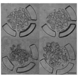
The U-shaped microstructures operate either temporarily, by pneumatic actuation, or permanently inside the device. Many of these U-shaped microstructures are usually integrated. The diameter of the spheroids depends on the size of the microstructure, while the relative position of the microstructures is essential for effective cell trapping.
In addition, it is possible to modulate the time of spheroid formation using the flow rate. However, high flow rates cause the cells to escape from the trap. On the other hand, in order to keep the spheroids inside the microstructures, the flow must be maintained, thus maintaining the necessary stagnation pressure.
Microwell-based Microfluidic spheroid formation chips (µSFC)
In general, a microwell-based µSFC needs a specified number of microwells and a microchannel network to deliver the culture medium. Microchannels should be designed in a way that can prevent undesirable spheroid escape from the microwells. Experimentally, it has been indicated that increasing the channel width or decreasing its height can limit spheroid escape.
In order to equalize flow rates across several microchannels, flow resistance must be the same through all of them. Therefore, if channels have the same width and height, their lengths must also be equal to satisfy this requirement. Sinuous channels, often used in concentration gradient generators (CGGs) as mixing channels, are appropriate to adjust channel length precisely within a smallarea of the chip. Such channels can thus be applied for flow control purposes rather than including valves within microfluidic chips. Desired flow rates must also take into account the number of cells existing in the culture environment and their corresponding requirements for oxygen, nutrients and other factors.
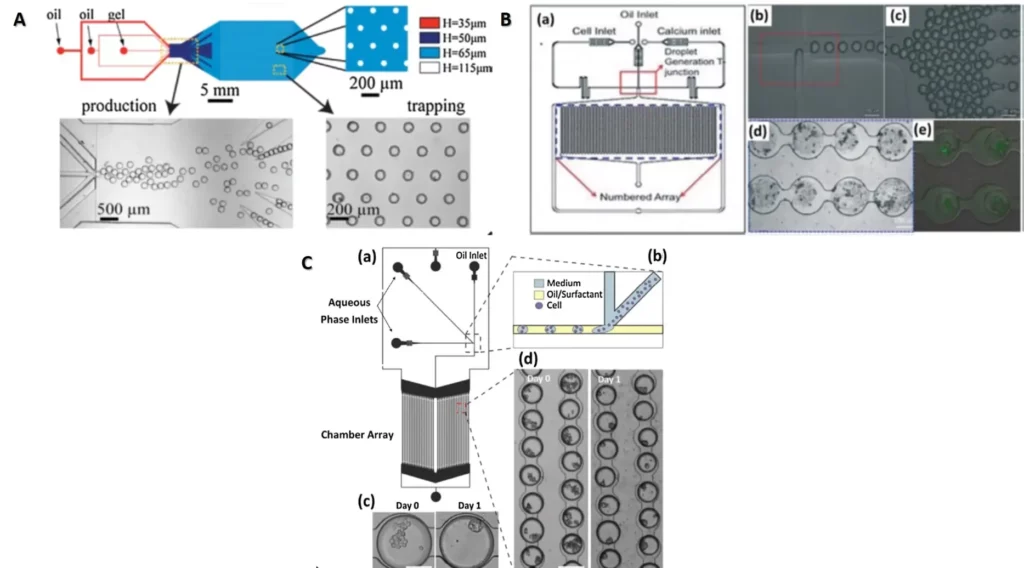
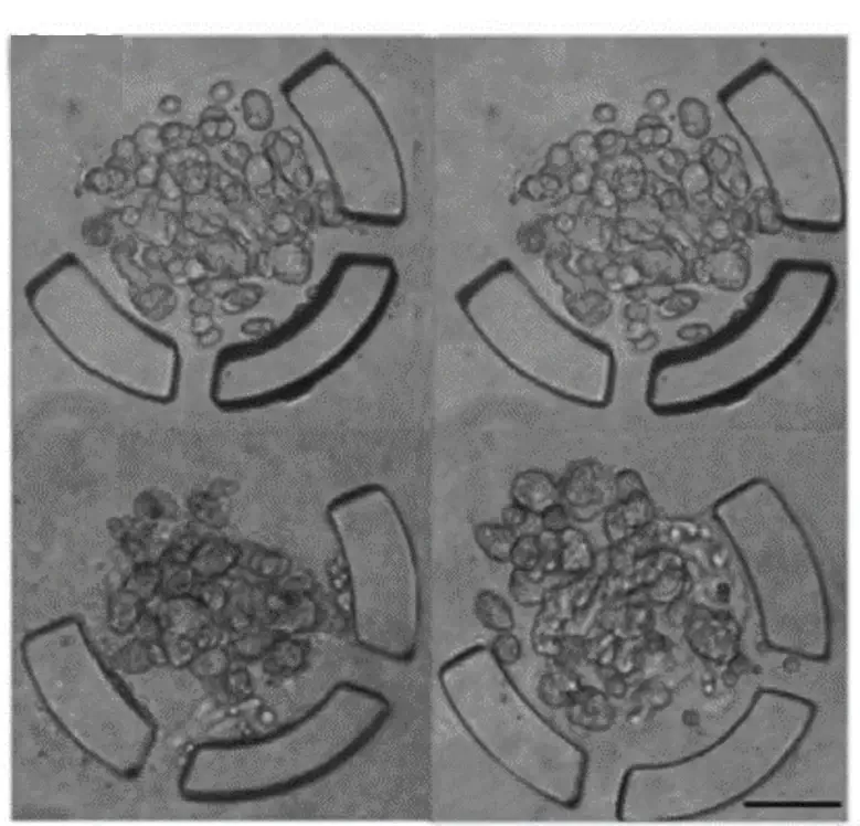
There are many devices that can be used to trap organised cells called spheroids or organoids. In the figure 3 we present some of these devices.
