Platforms based on microfabrication and microfluidics have been successfully utilized in a variety of applications such as drug discovery, polymer chain reaction (PCR), single-cell analysis or crystallization proteins to name a few. For all of these applications, producing droplets at controlled sizes as well as controlled generation rates appear as key factors in order to obtain interpretable, reliable and robust results. Indeed, droplet size can be affected by many factors such as interfacial tension or channel size.
Today, a wide range of geometries have been developed, allowing the generation of droplets in passive or active mode. In this review, we will focus on the most widely used droplet generation designs.
Passive and active modes
Passive mode
Microfluidic methods for forming droplets can be either passive or active. In passive methods, microfluidic two-phase flow is controlled by syringe pumps (that supply constant flow rates) or pressure regulators without additional energy input. During droplet formation, a part of the energy introduced from the syringe pumps or pressure controllers is converted into interfacial energy and thus facilitates the destabilization of the liquid-liquid interface, whereby discrete droplet shedding from the dispersed phase occurs [Seemann R. et al. 2012 Rep Prog Phys.]. Pratically, the fluid phase to be dispersed is driven into a microchannel by a pressure-driven flow in which the volume flow rate or the applied pressure is necessarily controlled. A second immiscible liquid is driven into a separate microchannel via an independently controlled flow. The two streams meet at the junction. The geometry of the junction and the volumetric flow rates of the two fluids determine the flow field, which deforms the interface [Christopher GF and Anna SL. 2007 J Phys Appl Phys].
Active mode
In active mode, it is possible to modulate the droplet generation with an additional energy input by active controls including external forces such as electric, magnetic, or centrifugal fields and internal forces like viscous and capillary forces. To be more precise, the energy imbalance modulates the nature of force balance on the interface for droplet generation.
The active droplet generation can either be induced by two types of forces: the modification of intrinsic forces or the introduction of additional forces. Additional forces are exploited by applying external electric, magnetic, and centrifugal fields, while modifying the intrinsic inertial, viscous, and capillary forces can be performed by manipulating the dynamic velocity and material properties, including viscosity, interfacial tension, channel wettability, and fluid density [Chong ZZ et al. 2016 Lab Chip.].
Droplet generation chip designs
Cross-flow with T-junction
We can talk about cross-flow when dispersed and continuous phase fluids meet at an angle θ between 0 and 180° (see Fig. 1). Generally, the cross-flow structure is associated with a T-junction. Thus, the dispersed and continuous fluids are fed orthogonally.
There are three regimes of microfluidic droplet generation with T-junction: the dripping regime, the squeezing regime, and the jetting regime (see Fig. 2). In principle, droplets generated with dripping mode are smaller than the channel dimension and highly monodisperse. For the squeezing regime, droplets are larger than the channel and monodisperse. Finally, with the jetting mode, the droplet generation is polydisperse.
The first advantage of the cross-flow is the ease with which droplets can be formed and the uniformity of the resulting droplets. Indeed, within a large range of flow rates, it is possible to obtain a regular and periodic droplet formation when a single T-shape channel is used. However, in some studies [Garstecki P et al. 2005 Nature Phys ; Barbier et al. 2006 Phys Rev.], it appears that droplets are not necessarily regular when multiple droplet generators are coupled with a single set of syringe pumps, they can appear as a critical issue in the case of a study where it is necessary to precisely control the droplet size.


Flow focusing
The flow focusing corresponds to the formation of dispersed droplets of a fluid in a continuous stream of other fluid. It exists two variants of geometric microfluidic flow-focusing systems: the simple cross junction and the cross junction followed by a constriction (also called nozzle). In addition, it is possible to distinguish a quasi-2D planar configuration (see Fig. 3 (i) (ii)) and an axisymmetry 3D configuration (see Fig. 3 (iii) (iv)).
Compared to planar flow-focusing devices, 3D axisymmetric flow-focusing devices avoid issues such as wetting of channel walls by the dispersed phase, therefore producing monodisperse droplets using higher throughputs.
Then, as for the cross-flow geometry, it is possible to distinghish three different modes : squeezing, dripping and jetting modes (see Fig. 4). The advantage of using flow focusing lies in its simplicity in terms of geometry, hence its many design variations. However, there is not a simple mechanistic model available that can predict droplet size over a wide range of flow conditions. An other well-known problem is the unwanted merging of droplets, which can be prevented by the use of surfactants. However, surfactants can also interfere or inhibit the biochemical reactions.


Multichannel dynamic interface
The most classically used geometries in microfluidic droplets are flow-focusing and T junctions. It should be understood that these techniques require increased technical skills and specialized equipment which can be a barrier for laboratories not specialized in microfluidics. Besides, the droplet size can be affected by many factors such as fluid viscosity, interfacial tension, channel size, etc.
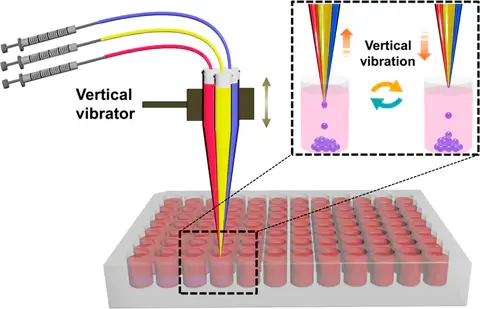
Here, a simple active (electrical) technique for generating droplets using the dynamic interfacial shearing driven by a mechanical device (see Fig. 1) is used. Pratically, liquid components converge on the nozzle and generate droplets with the interfacial shear due to the vibration of a multichannel capillary.


LOOKING TO SCALE UP YOUR DROPLET PRODUCTION?
Explore our scalable solutions designed to meet the demands of high-throughput droplet generation with easeOne of the first advantages is that the device is simply based on a cheap vibrator and handmade tapered multichannel capillary, which is easy to assemble and usable by everyone without any expertise in droplet generation. The other advantage is that the technique exhibits excellent performance in generating uniform droplets with predesigned sizes and components. Although the manufacturing and assembly are easy, the fact that the microchannels are made by hand can represent a bias in the reproducibility of the device but can also influence the size of the droplets generated by two different devices using the same settings. Moreover, this technique is limited to a small number of biological applications such as bacteria studies because the droplet diameter decreases as the capillary number increases, due to increased viscous stresses acting to deform the droplet.
Conclusion
In this review, we saw a very small part of existing geometries and their variations to generate microfluidic droplets. Each of them has its unique characteristics in terms of flow instabilities, droplet size, or droplet behaviors. For an effective droplet production with the desired outcome, it is important to have a deep understanding of the effects of viscous, inertial, and capillary forces. Thus, as the precise dependence of droplet size on the flow parameters depends on the specific geometry considered, it is important to take into account the precise needs and constraints of the desired research application to choose the perfect droplet generation design.
