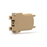


This inline degassing chamber removes bubbles from your microfluidic systems. Compatible with aqueous and organic fluids, it can eliminate air bubbles in flows ranging from 0.4 to 4 mL/min.
Pack of 1 unit, available in different chamber sizes.
General
Dissolved gases in liquids can form bubbles due to changes in pressure or temperature, which can negatively affect the stability and performance of your fluidic systems, by blocking channels and causing disturbances. In microfluidic setups, using a degassing chamber helps maintain a precise and controlled flow path.
With its low internal volume, the inline degassing chamber eliminates dissolved gases and already-formed bubbles in precision low-flow applications such as microfluidics. Its semi-permeable inner tubing allows air removal through the connection of a vacuum or negative pressure source to the chamber.
Available with different internal volumes for recommended flow rates as follows:
- 100 µL - 0.4 mL/min
- 480 µL - 2 mL/min
- 670 µL - 2.8 mL/min
- 925 µL - 4 mL/min
Features & Benefits
- High degassing performance at low flow rates
- Great chemical resistance to a wide variety of fluids
- Inline device to avoid perturbations in the fluidic system
- Compact device and small internal volumes
Principle & Instructions
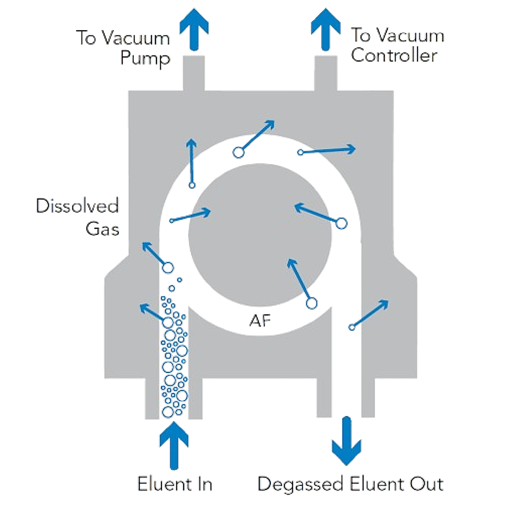
When a solution containing gas or bubbles flows through the degassing chamber, air is expelled through its porous Teflon AF® membrane while the liquid exits the chamber, with no leakage. This process relies on the differential pressure between the inner and the outer sides of the chamber membrane, which can be increased by adding a vacuum line to the device.
- Place the degasser before the pump and your microfluidic device/system. The liquid sample has to be aspirated from the outlet of the chamber to maximize performance.
- Connect your fluidic system to the inlet and outlets of the chamber through 1/4-28 adapters (not included).
- Connect the vacuum ports to your vacuum or negative pressure pump via the embedded barb connectors for 1/8" ID flexible tubing.
- Ensure that all connections are leak-free.
- Start your experiments!

Content
1x Inline degassing chamber
Specifications
| Internal volume | 100 µL | 480 µL | 670 µL | 925 µL |
| Recommended flow rate | 0.4 mL/min | 2 mL/min | 2.8 mL/min | 4 mL/min |
| Max flow rate | 10 mL/min | |||
| Pressure rating max | N/A | 2 bar (30 psi) | ||
| Number of fluid channels | 1 | |||
| Liquid connection ports | Female 1/4-28 flat-bottom UNF | |||
| Vacuum connection ports | Barb for 1/8" ID flexible tubing | |||
| Compatible fluids | Organic solvents, pH 1 to 14, organic-aqueous mixtures, high salinity and detergent-containing fluids | |||
| Chamber material | PEEK | |||
| Membrane material | Systec AF | |||
| Wetted material | FEP, PEEK, PTFE | |||
| Dimensions (L×W×H) | 7.4 x 1.3 x 4.6 cm | |||
Documentation
How Are Air Bubbles Formed in Microfluidics ?
This inline degassing chamber removes bubbles from your microfluidic systems. Compatible with aqueous and organic fluids, it can eliminate air bubbles in flows ranging from 0.4 to 4 mL/min.
Pack of 1 unit, available in different chamber sizes.
General
Dissolved gases in liquids can form bubbles due to changes in pressure or temperature, which can negatively affect the stability and performance of your fluidic systems, by blocking channels and causing disturbances. In microfluidic setups, using a degassing chamber helps maintain a precise and controlled flow path.
With its low internal volume, the inline degassing chamber eliminates dissolved gases and already-formed bubbles in precision low-flow applications such as microfluidics. Its semi-permeable inner tubing allows air removal through the connection of a vacuum or negative pressure source to the chamber.
Available with different internal volumes for recommended flow rates as follows:
- 100 µL - 0.4 mL/min
- 480 µL - 2 mL/min
- 670 µL - 2.8 mL/min
- 925 µL - 4 mL/min
Features & Benefits
- High degassing performance at low flow rates
- Great chemical resistance to a wide variety of fluids
- Inline device to avoid perturbations in the fluidic system
- Compact device and small internal volumes
Principle & Instructions
When a solution containing gas or bubbles flows through the degassing chamber, air is expelled through its porous Teflon AF® membrane while the liquid exits the chamber, with no leakage. This process relies on the differential pressure between the inner and the outer sides of the chamber membrane, which can be increased by adding a vacuum line to the device.
- Place the degasser before the pump and your microfluidic device/system. The liquid sample has to be aspirated from the outlet of the chamber to maximize performance.
- Connect your fluidic system to the inlet and outlets of the chamber through 1/4-28 adapters (not included).
- Connect the vacuum ports to your vacuum or negative pressure pump via the embedded barb connectors for 1/8" ID flexible tubing.
- Ensure that all connections are leak-free.
- Start your experiments!

Content
1x Inline degassing chamber
Specifications
| Internal volume | 100 µL | 480 µL | 670 µL | 925 µL |
| Recommended flow rate | 0.4 mL/min | 2 mL/min | 2.8 mL/min | 4 mL/min |
| Max flow rate | 10 mL/min | |||
| Pressure rating max | N/A | 2 bar (30 psi) | ||
| Number of fluid channels | 1 | |||
| Liquid connection ports | Female 1/4-28 flat-bottom UNF | |||
| Vacuum connection ports | Barb for 1/8" ID flexible tubing | |||
| Compatible fluids | Organic solvents, pH 1 to 14, organic-aqueous mixtures, high salinity and detergent-containing fluids | |||
| Chamber material | PEEK | |||
| Membrane material | Systec AF | |||
| Wetted material | FEP, PEEK, PTFE | |||
| Dimensions (L×W×H) | 7.4 x 1.3 x 4.6 cm | |||
Documentation
How Are Air Bubbles Formed in Microfluidics ?


